Vfd (variable frequency drive) Circuit configuration of conventional single inverter motor drive Three phase inverter circuit diagram – diy electronics projects
Easy Inverter Circuit with 2SC1815 Transistors
12v dc to 220v ac inverter circuit & pcb Easy inverter circuit with 2sc1815 transistors Inverter timer 230v 240v
Circuit inverter transistors circuits explanation
7 simple inverter circuits you can build at homeInverter ac circuit diagram Inverter circuit diagram power 1000w wiring 12v 220v schematic dc npower watt 500w mosfet 110v ac wave circuits inverters sine12v to 230v inverter circuit diagram using 555 timer ic » inverters.
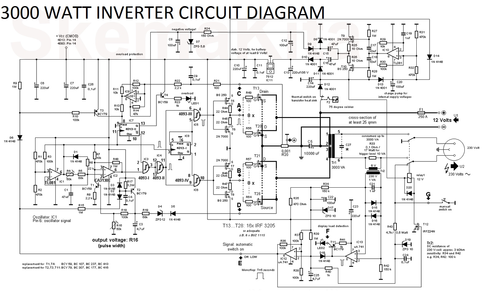
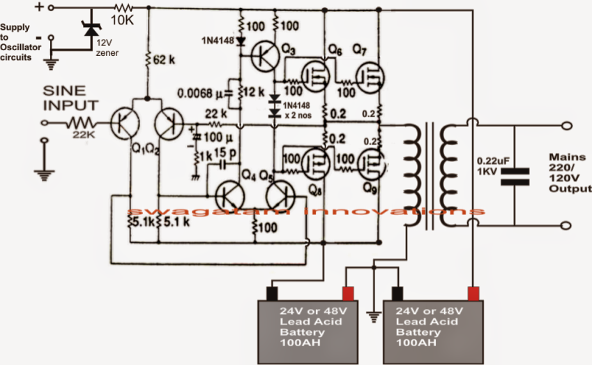
Simple inverter circuit diagramInverter circuit 2000w diagram power high resolution click Interlocking gate drivers for improving the robustness of three-phaseThree phase inverter circuit diagram.
How to build a power inverter circuit
Inverter 220v how2electronicsVfd inverter component Automatic power inverter circuit diagramVfd motor drive circuit diagram.
Simple mosfet inverter circuit diagramGrid inverter circuit diagram Wiring diagram vsdVariable frequency drives explained.
Motor controller
Free 5kva inverter circuit diagramCircuit inverter control diagram drive seekic amplifier Inverter circuit 12v circuits 230v coupledInverter circuit oscillator 200w watts.
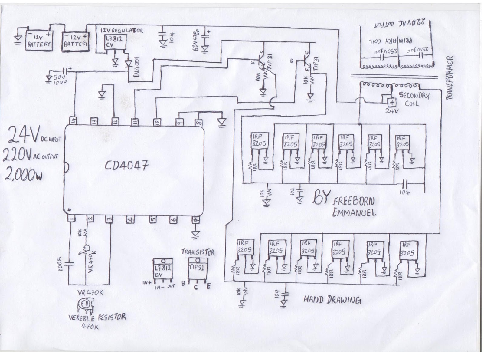
Guide complet des schémas de circuits des onduleurs2000w inverter circuit diagram 1000w power inverter circuit designInverter diagram circuit 24v 2kva watt 2000 build electrical schematics board simple transformer schematic power wiring electronic dc ac fridge.

Variable frequency drive wiring diagram
A repair method for vfd (variable-frequency drive) ic short circuit faultHow to build a 2kva inverter circuit diagram : 2000 watt inverter Electric wiring diagram for frequency converter???Simple inverter circuit diagram.
Vfd or inverter drive power component schematicPhase three gate inverter inverters isolated drivers ti industrial vfd robustness interlocking improving schematic 3phase figure technical Ac inverter circuit diagramFrequency inverter circuit diagram.

Inverter phase circuit three 120 degree mode conduction diagram dc dilip raja nov
Power inverter circuit using 7473 icHow to build 200w inverter circuit diagram project Inverter control and drive circuit diagram.
.


Inverter Ac Circuit Diagram
Grid Inverter Circuit Diagram
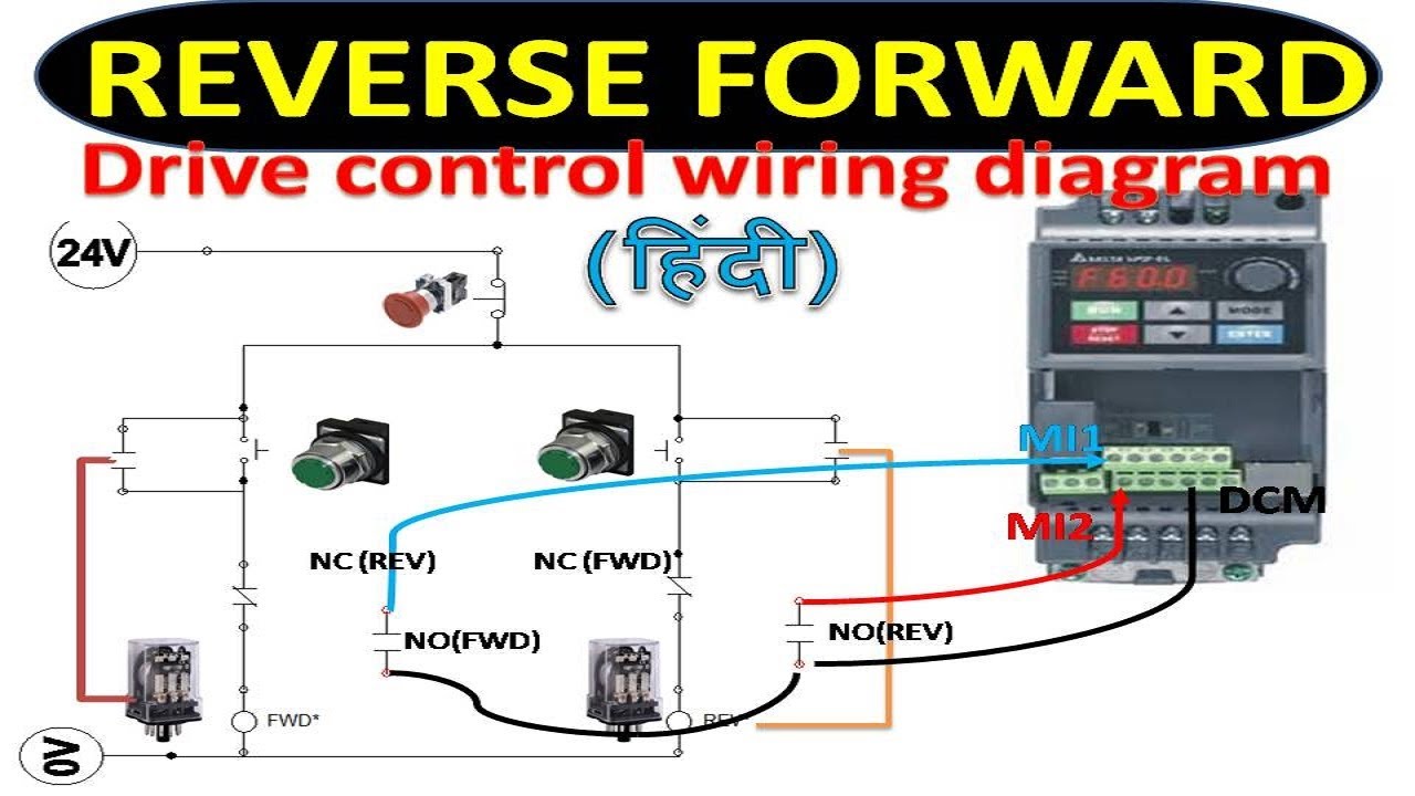
Wiring Diagram Vsd

Three Phase Inverter Circuit Diagram – DIY Electronics Projects

Frequency Inverter Circuit Diagram
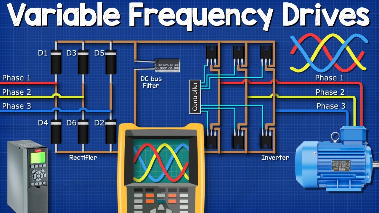
Variable Frequency Drives Explained - VFD Basics IGBT inverter - YouTube

12V to 230V Inverter Circuit Diagram using 555 timer IC » Inverters